Engineering equations

How to use this tool.
1. Select the variable you are trying to find from the list.
2. The equations relating to that variable are displayed.
3. Choose the equation which suits your application.
F = m a
v = u + a t
(a)acceleration, (F)force, (m)mass, (t)time, (u)initial velocity, (v)velocity
R = ρ l / A
B = Ѱ / A
(R)resistance, (ρ)resistivity, (l)length, (A)area
Q = I t
(Q)charge, (I)current, (t)time
V = I R
P = I V
P = I2 R
W = I V t
W = I2 R t
Q = I t
e = -L (Δ I / Δ t) (self inductance)
(V)voltage, (I)current, (R)resistance, (P)power, (W)work, (t)time, (Q)charge, (e)electromotive force, (L)inductance, (Δ)change in
ρ = m / V
(ρ)resistivity, (m)mass, (V)volume
T = F d
W = F d
v = d / t
(T)torque, (F)force, (d)distance, (W)work, (v)velocity or speed, (t)time
e = B l v
e = Δ Ѱ / Δ t (For a coil)
e = -N (Δ Ѱ / Δ t) N = Number of turns (For a coil)
e = -L (Δ I / Δ t) (self inductance)
(e)electro motive force, (B)flux density, (l)length, (v)velocity or speed, (Δ)change in, (Ѱ)flux, (t)time, (N)number of turns, (L)inductance, (I)current
B = Ѱ / A
e = Δ Ѱ / Δ t (For a coil)
e = -N (Δ Ѱ / Δ t) N = Number of turns (For a coil)
(e)electro motive force, (A)area, (B)flux density, (Δ)change in (Ѱ)flux, (t)time, (N)number of turns
B = Ѱ / A
e = B l v
(e)electro motive force, (A)area, (B)flux density, (Ѱ)flux, (l)length, (v)velocity or speed
F = m a
T = F d
W = F d
(F)force, (m)mass, (a)acceleration, (T)torque, (d)distance, (W)work
w = m g
(w)weight, (m)mass, (g)acceleration due to gravity
e = -L (Δ I / Δ t) (self inductance)
(e)electromotive force, (L)inductance, (Δ)change in, (I)current, (t)time
R = ρ l / A
e = B l v
(R)resistance, (ρ)resistivity, (l)length, (A)area, (e)electromotive force, (B)flux density, (v)velocity or speed
F = m a
p = m v
ρ = m / V
w = m g
(F)force, (m)mass, (a)acceleration, (p)momentum, (v)velocity or speed, (ρ)resistivity, (V)volume, (w)weight, (g)acceleration due to gravity
p = m v
(p)momentum, (m)mass, (v)velocity or speed
P = W / t
P = I V
P = I2 R
P = V2 / R
(P)power , (W)work , (t)time , (I)current , (V)voltage , (R)resistance
V = I R
R = ρ l / A
Rparrallel = 1 / (1 / R1 + 1 / R2 + 1 / Rn )
P = I2 R
P = V2 / R
W = I2 R t
W = V2 t / R
(P)power , (W)work , (t)time , (I)current , (V)voltage , (R)resistance, (ρ)resistivity, (l)length, (A)Area
Rparrallel = 1 / (1 / R1 + 1 / R2 + 1 / Rn )
(R)resistance
R = ρ l / A
(R)resistance, (ρ)resistivity, (l)length, (A)Area
v = d / t
P = W / t
v = u + a t
W = I V t
W = I2 R t
W = V2 t / R
Q = I t
e = Δ Ѱ / Δ t (For a coil)
e = -N (Δ Ѱ / Δ t) N = Number of turns (For a coil)
e = -L (Δ I / Δ t) (self inductance)
(v)velocity, (d)distance, (u)initial velocity, (a)acceleration, (Ѱ)flux,
(N)number of turns, (V)voltage, (I)current, (R)resistance, (P)power,
(W)work, (t)time, (Q)charge, (e)electromotive force, (L)inductance, (Δ)change in
T = F d
(T)torque, (f)force, (d)distance
v = u + a t
(v)velocity, (u)initial velocity, (a)acceleration, (t)time
V = I R
P = I V
P = V2 / R
W = I V t
W = V2 t / R
(V)voltage, (I)current, (R)resistance, (P)power,
(W)work, (t)time
p = m v
v = d / t
v = u + a t
e = B l v
(v)velocity, (d)distance, (u)initial velocity, (a)acceleration,
(t)time, (e)electro motive force, (B)flux density, (l)length, (p)momentum, (m)mass
ρ = m / V
(V)volume, (ρ)density, (m)mass
w = m g
(w)weight, (m)mass, (g)acceleration due to gravity
W = f d
W = I V t
W = I2 R t
W = V2 t / R
(W)work, (f)force, (d)distance, (I)current, (V)voltage, (t)time, (R)resistance
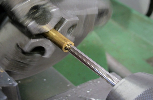
Speed and feed calculators
This tool will allow you to find the correct speed and feed for all High-Speed Steel (HSS) or Tungsten Carbide cutting tools.
Select the material and enter the cutter dimensions and number of teeth where required.
Please note:
- Consideration must be given to the size and condition of the machine as this can impact cutting speed, feed and depth of cut.
- For reaming run at 1/2 of the calculated speed
- For countersunk and counterbored holes run at 1/3rd the cutting speed
Metric Imperial Converter

This tool allows you to convert millimetres to inches and vice versa quickly and easily.
Select the conversion you require, input the dimension you need to convert and then press calculate. Your result will then be displayed.
Metric sine bar calculator
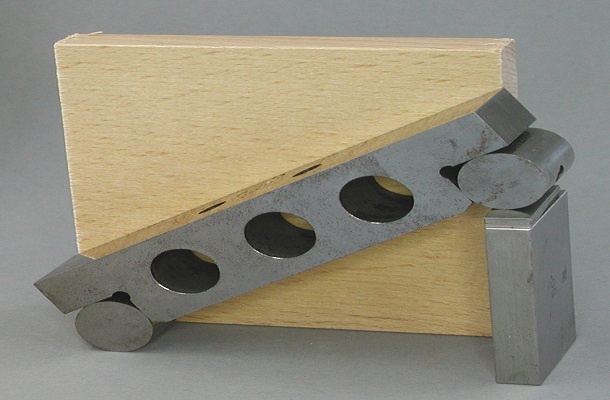
This tool allows you to calculate the slip gauge pile required for metric sine bars. Insert the required angle in degrees and the distance between centres in millimetres and select calculate.
The slip block pile is:mm.
Imperial sine bar calculator
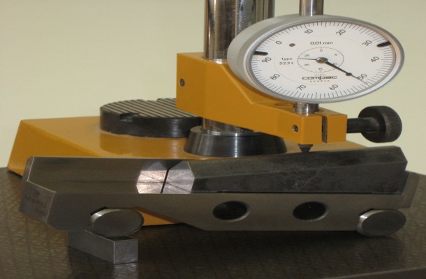
This tool allows you to calculate the slip gauge pile required for imperial sine bars. Insert the required angle in degrees and the distance between centres in inches and select calculate.
The slip block pile is:".
Tapping & Clearance Drill Sizes
This chart gives the tapping and clearance drilling sizes for a range of metric screwthreads.
Select the thread you require and read the tapping and clearance drills from the charts.
Reamer Hole Size Chart
This chart can be used to determine the drill sizes for a range of metric and imperial reamers. Select the size of the reamed hole you require and read the amount to reduce the core drill by from the chart.
Lathe Tool Geometry

This chart can be used to determine the geometry of cutting tools to be used on centre lathes for a variety of material types.
Lathe Tool Geometry
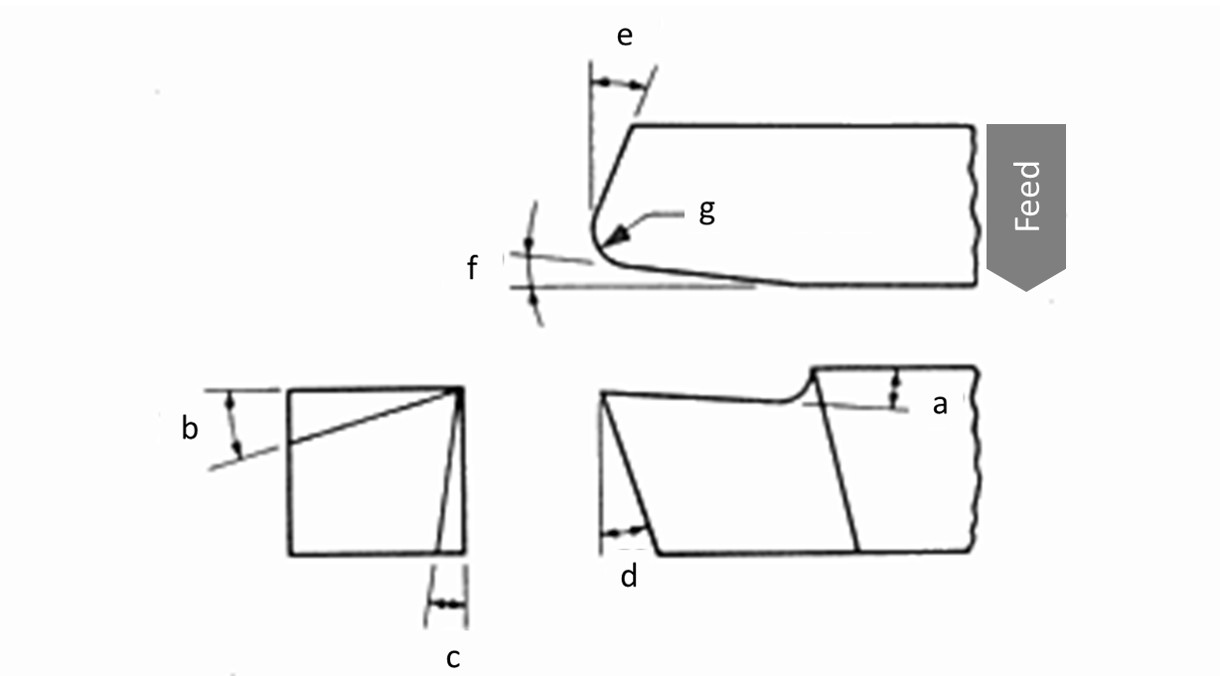
Back Rake = a
Side Rake = b
End Relief = c
Side Relief = d
End Cutting Edge = e
Side Cutting Edge = f
Nose Radius =g
Generally speaking, the larger the nose radius the better the surface finish
| (a)(°) | (b)(°) | (c)(°) | (d)(°) | (e)(°) | (f)(°) | (g)(mm) | |
|---|---|---|---|---|---|---|---|
| Aluminium & Magnesium alloys | 20 | 15 | 12 | 10 | 5 | 5 | 3 |
| Copper alloys | 5 | 10 | 8 | 8 | 5 | 5 | 3 |
| Steels | 10 | 12 | 5 | 5 | 15 | 15 | 3 |
| Stainless Steels | 5 | 8-10 | 5 | 5 | 15 | 15 | 3 |
| High temperature alloys | 0 | 10 | 5 | 5 | 15 | 15 | 3 |
| Refractory alloys | 0 | 20 | 5 | 5 | 5 | 5 | 3 |
| Titanium alloys | 0 | 5 | 5 | 5 | 15 | 15 | 3 |
| Cast irons | 5 | 10 | 5 | 5 | 15 | 15 | 3 |
| Thermo plastics | 0 | 0 | 20-30 | 15-20 | 10 | 10 | 3 |
| Thermosets | 0 | 0 | 20-30 | 15-20 | 10 | 10 | 3 |
Fit Chart
This chart can be used to calculate the dimensions for a given fit tolerance on an engineering drawing.
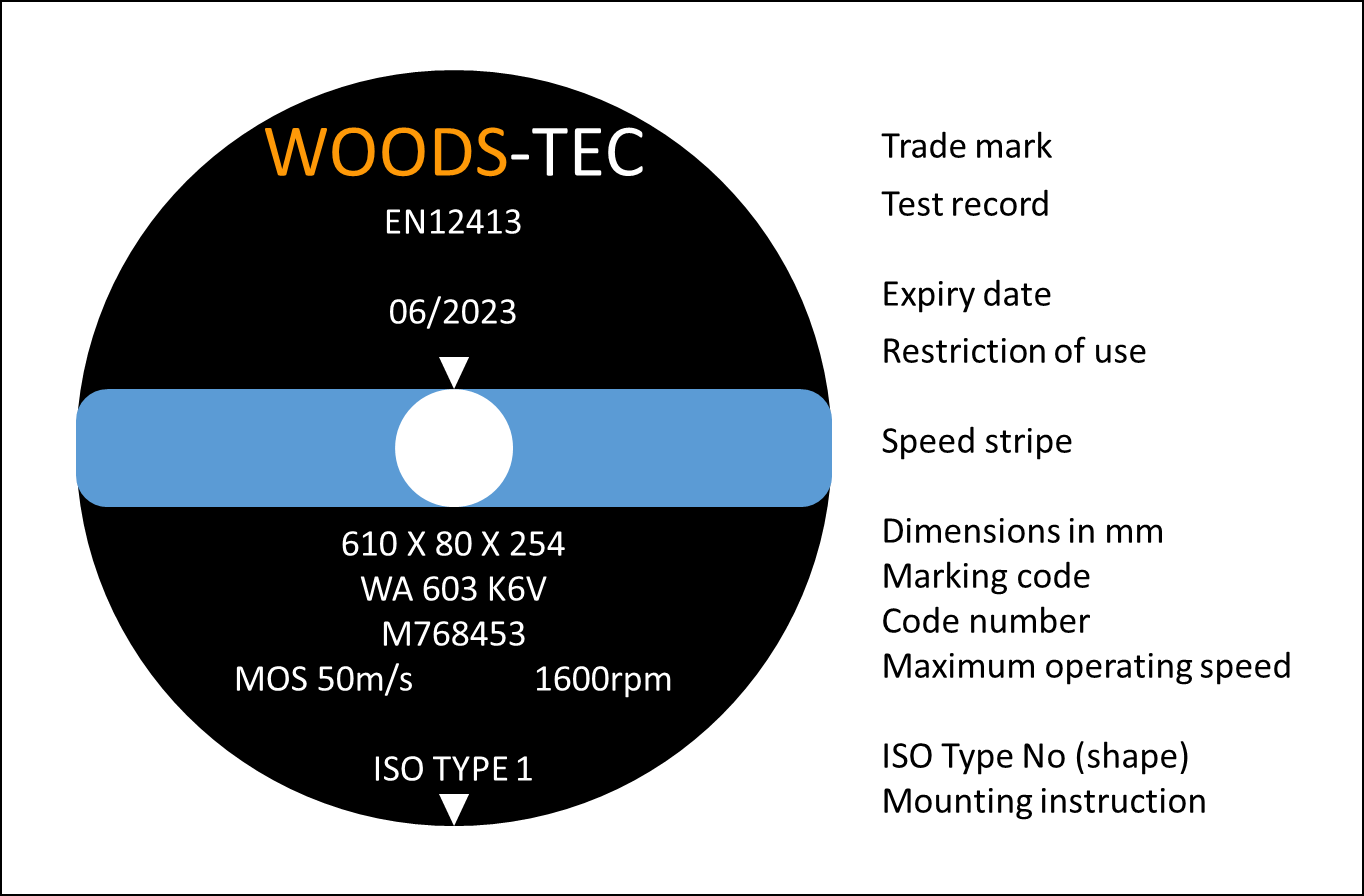
Abrasive wheel selection

This chart can be used to determine the correct type of abrasive wheel for a range of different materials.
Abrasive wheel selection chart
| Marking | Marking Codes | Applications |
|---|---|---|
| Abrasive Material | A – regular aluminium oxide | Typically used for grinding; carbon steel, alloy steel, high speed steel, annealed malleable iron, wrought iron, and bronzes. |
| WA – white aluminium oxide | ||
| FA – semi-friable aluminium oxide | ||
| PA – pink aluminium oxide | ||
| SA (HA) – single crystal aluminium oxide | ||
| SD – synthetic diamond | Typically used to grind very hard materials such as ceramic's and tungsten carbide. | |
| ASD – synthetic diamond, metal coating | ||
| C – black silicon carbide | Typically used for grinding cast iron, non-ferrous metals and non-metallic materials. | |
| GC – green silicon carbide | ||
| RC – mixture of C and GC | ||
| Grit Size | (Coarse) 10 to 1200 (Fine) | Hard, brittle materials generally require a wheel with a fine grit size and a softer grade. |
| Grade | (Soft) A to X (Hard) | |
| Structure | (Dense) 1 to 14 (Open) | Softer materials benefit from a more open structure to prevent wheel loading |
| Bonding | B – resinoid | Organic bonding, is usually made from bonding materials such as rubber and have good shock resistant and self dressing properties. This type of wheel is typically used for non precision cutting. |
| R – rubber | ||
| E – epoxy | ||
| O – MgO | Inorganic bonding, usually creates a harder wheel better suited to precision applications as they hold their shape better. | |
| V – vitrified | ||
| M – metal | ||
| EP – electroplated |
CONTACT
Need expert support to fill a training position? Book a professional trainer today! Our experienced instructors specialize in a wide range of technical disciplines, including Electrical Systems, Mechanical Engineering, Robotics, PLC Programming, Fluid Power, and Precision Machining. Empower your team with hands-on, industry-relevant training tailored to your needs. Reach out now to secure the expertise you’re looking for!